Implementing Belcour’s Thin-Film BRDF
Motivation
In the Disney BSDF lecture I met the idea of a complex index of refraction. Disney only uses Schlick’s approximation, but that glimpse made me curious: what is a complex \(η\) and where does it come from physically? Mid-quarter I was fascinated by wave-optics phenomena such as thin-film iridescence. Belcour’s paper looked daunting on first pass, yet the final project was a perfect excuse to dive in.
Key references I leaned on repeatedly:
- The original paper — A Practical Extension to Microfacet Theory for the Modeling of Varying Iridescence
- Prof. Matthew D. Schwartz — WAVES lecture notes
- Bob Eagle’s E-and-M YouTube lectures
The post follows the route I wish I’d had: physics → rendering theory → implementation.
Physical Model for Thin-Film Interference
This was the most fun (and the deepest rabbit-hole) — yet nothing beats seeing an equation-heavy model reproduce the hues of real steel.
Light as a Wave
Classical ray tracing treats light as straight-line rays — fine when obstacles are large relative to wavelength, but it misses interference. Light is in fact an electromagnetic wave; Fig. 1 shows orthogonal \(𝐄\) and \(𝐁\) fields.
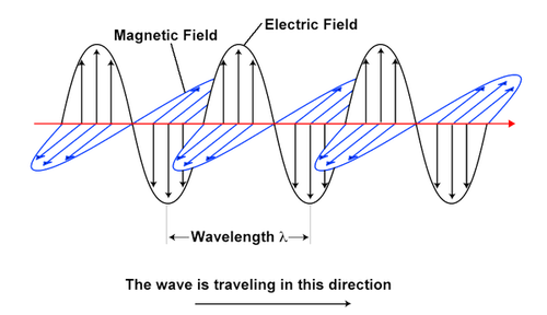
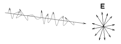
Reflection/refraction are simply one wave meeting a medium boundary, its behaviour governed by Maxwell’s equations
\[\nabla\!\cdot\mathbf E = \frac{\rho}{\varepsilon_0}, \quad \nabla\!\cdot\mathbf B = 0, \quad \nabla\times\mathbf E = -\frac{\partial\mathbf B}{\partial t}, \quad \nabla\times\mathbf B = \mu_0\mathbf J + \mu_0\varepsilon_0\frac{\partial\mathbf E}{\partial t}.\]From them we derive the plane-wave solution
\[\mathbf E(z,t) = E_0\,\hat{\mathbf x}\cos(kz-\omega t),\qquad \mathbf B(z,t) = B_0\,\hat{\mathbf y}\cos(kz-\omega t),\]or, compactly,
\[\mathbf E(\mathbf r,t)=\Re\{\mathbf E_0\,e^{i(\mathbf k\!\cdot\!\mathbf r-\omega t)}\}.\]That complex form foreshadows the complex reflection coefficient.
Reflection & Refraction
At a boundary the tangential \(𝐄\) and \(𝐇\) components must satisfy continuity conditions (from the integral Maxwell form).
Wave-front matching yields Snell’s law
To obtain amplitudes we return to those boundary conditions, and derive the Fresnel amplitude coefficients
\[r_\perp = \frac{\cos\theta_i - η\cos\theta_t}{\cos\theta_i + η\cos\theta_t},\qquad r_\parallel = \frac{-η\cos\theta_i + \cos\theta_t}{η\cos\theta_i + \cos\theta_t},\]with \(η = η_2/η_1\) (and analogous \(t_\perp\), \(t_\parallel\)).
Power, not amplitude, matters for radiance:
Complex Index of Refraction
For conductors the material conductivity \(σ\) gives
\[η = \sqrt{\Bigl(\varepsilon' + i\,\frac{σ}{\omega\varepsilon_0}\Bigr)\mu_r}\;=\;η_R+iη_I ,\]so \(η\) is complex; the imaginary part models absorption (skin-depth attenuation).
Thin-Film Interference
A thin film adds a second interface (Fig. 3).
Two closely spaced reflected rays acquire a phase difference
creating interference.
Summing all paths (the Airy summation)
yields the closed-form
\[r = r_{12} + \frac{t_{12} r_{23} t_{21}\,e^{i\Delta\phi}}{1 - r_{21} r_{23}\,e^{i\Delta\phi}} ,\]and, for un-polarized light,
\[R = \tfrac12\!\left(|r_\perp|^{2} + |r_\parallel|^{2}\right).\]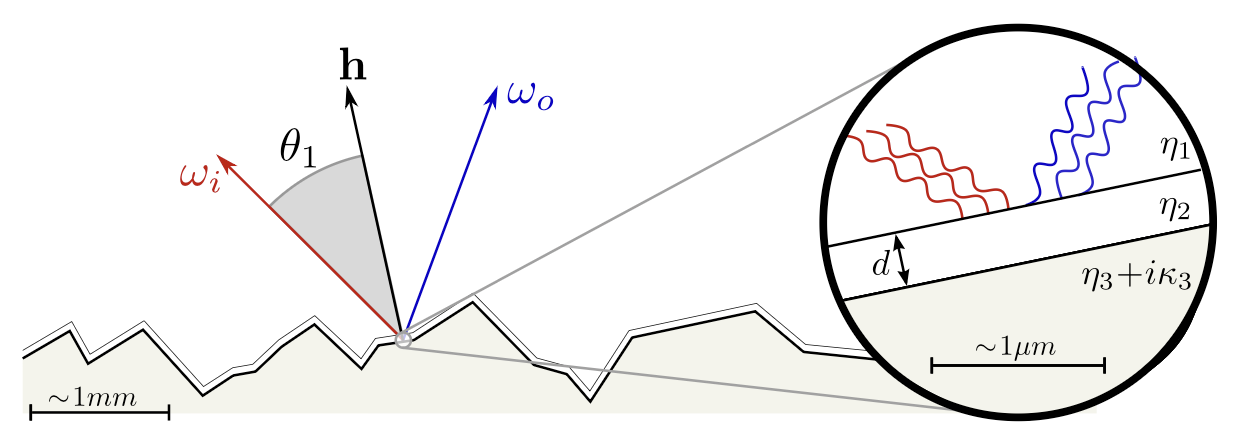
Rendering
BRDF Model
Belcour replaces the Schlick Fresnel term in the micro-facet BRDF with Airy reflectance \(R\):
\[\rho(\omega_o,\omega_i;\lambda)= \frac{D(\mathbf h)\,G(\omega_o,\omega_i)\,R(\mathbf h\!\cdot\!\omega_i;\lambda)} {4(\omega_o\!\cdot\!\mathbf n)\,(\omega_i\!\cdot\!\mathbf n)}.\]Because \(R\) depends on wavelength \(\lambda\), an RGB renderer must spectrally integrate it.
Spectral Integration
Human cones integrate spectrum into three LMS values, converted to RGB.
Analogously we pre-integrate BRDF & lights per band:
so only the reflectance term needs integration:
\[R_j(\mathbf h\!\cdot\!\omega_i)= \int R(\mathbf h\!\cdot\!\omega_i;\lambda)\, \frac{s_j(\lambda)}{\|s_j\|}\,d\lambda .\]Belcour’s Fourier Solution
Re-writing the Airy series as
\[R = C_0 + 2\sum_{m=1}^{\infty}C_m\cos(m\Phi),\]and assuming Fresnel amplitude/phase constant per band, a change of variable to frequency \(\nu\) plus Parseval gives the analytical band-integrated result
\[\boxed{ R_j = C_0 + 2\sum_{m=1}^{\infty}C_m \begin{bmatrix}\cos(m\phi_2)\\\sin(m\phi_2)\end{bmatrix}^{\!\!T} \begin{bmatrix}\Re_j(m\mathcal D)\\\Im_j(m\mathcal D)\end{bmatrix}}.\]\(\Re_j,\Im_j\) are the real/imaginary parts of the Fourier-transformed sensor curves, tabulated or Gaussian-fitted.
Implementation
I added a new material in La Jolla Renderer:
struct IridescentRoughConductor {
    Texture<Real> roughness;
    Texture<Real> anisotropic;
    Texture<Spectrum> film_texture;

    // Conductor base
    Real eta;   // real part
    Real k;     // extinction coeff.

    // Thin-film layer
    Real film_eta;
    Real min_thickness;   // nm
    Real max_thickness;   // nm
};
- Replaced the Cook–Torrance Fresnel with the analytic \(R_j\) above (using \(m\in[1,3]\)).
- Transmittance is \(T=1-R\) per energy conservation.
- Gaussian fits and look-up tables were ported from the authors’ Mitsuba plugin.
Scene & Results
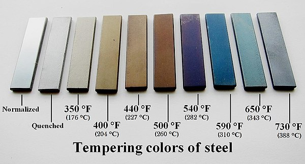
Reference photos of differentially tempered steel:
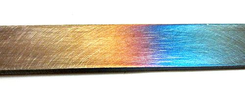
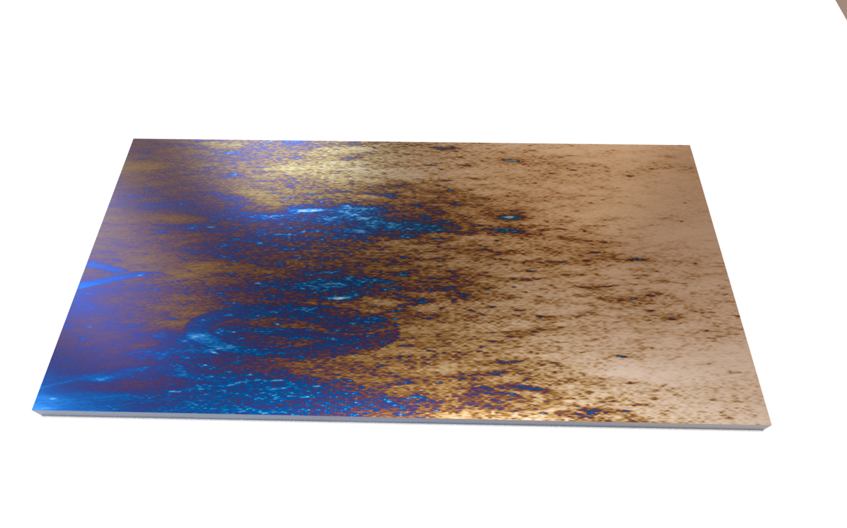
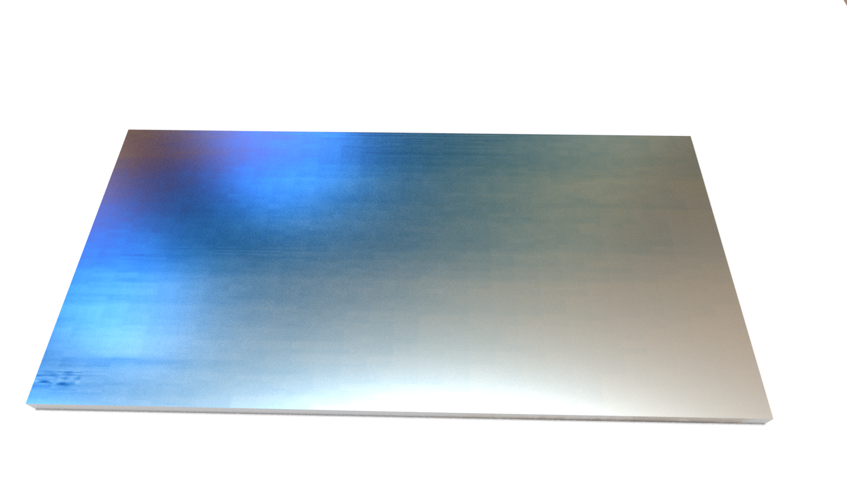
Rendered in La Jolla (large dome light above, iron base \(η=2.7, κ=2.8\), oxide film \(η=2.9\), thickness 10–70 nm):
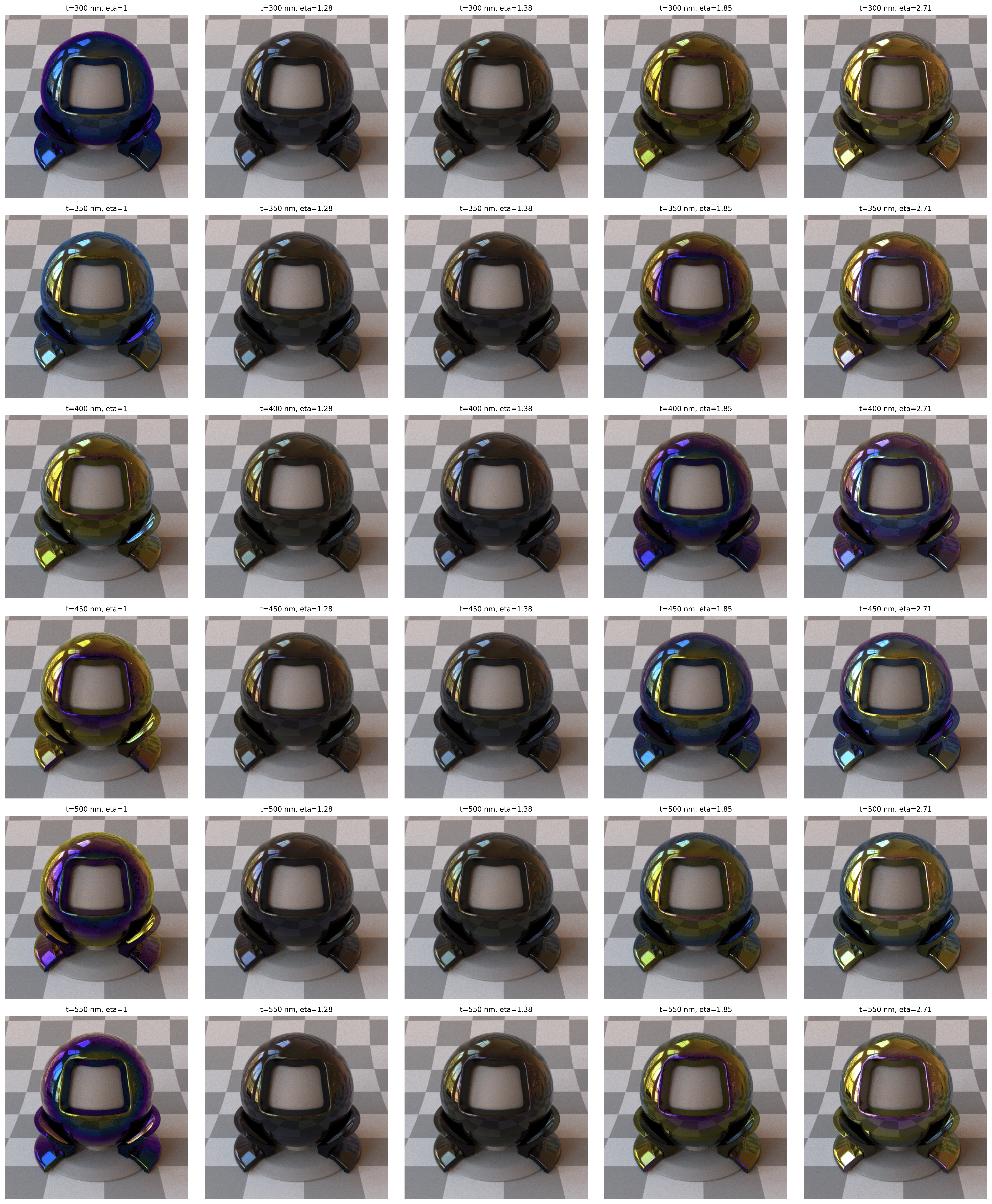
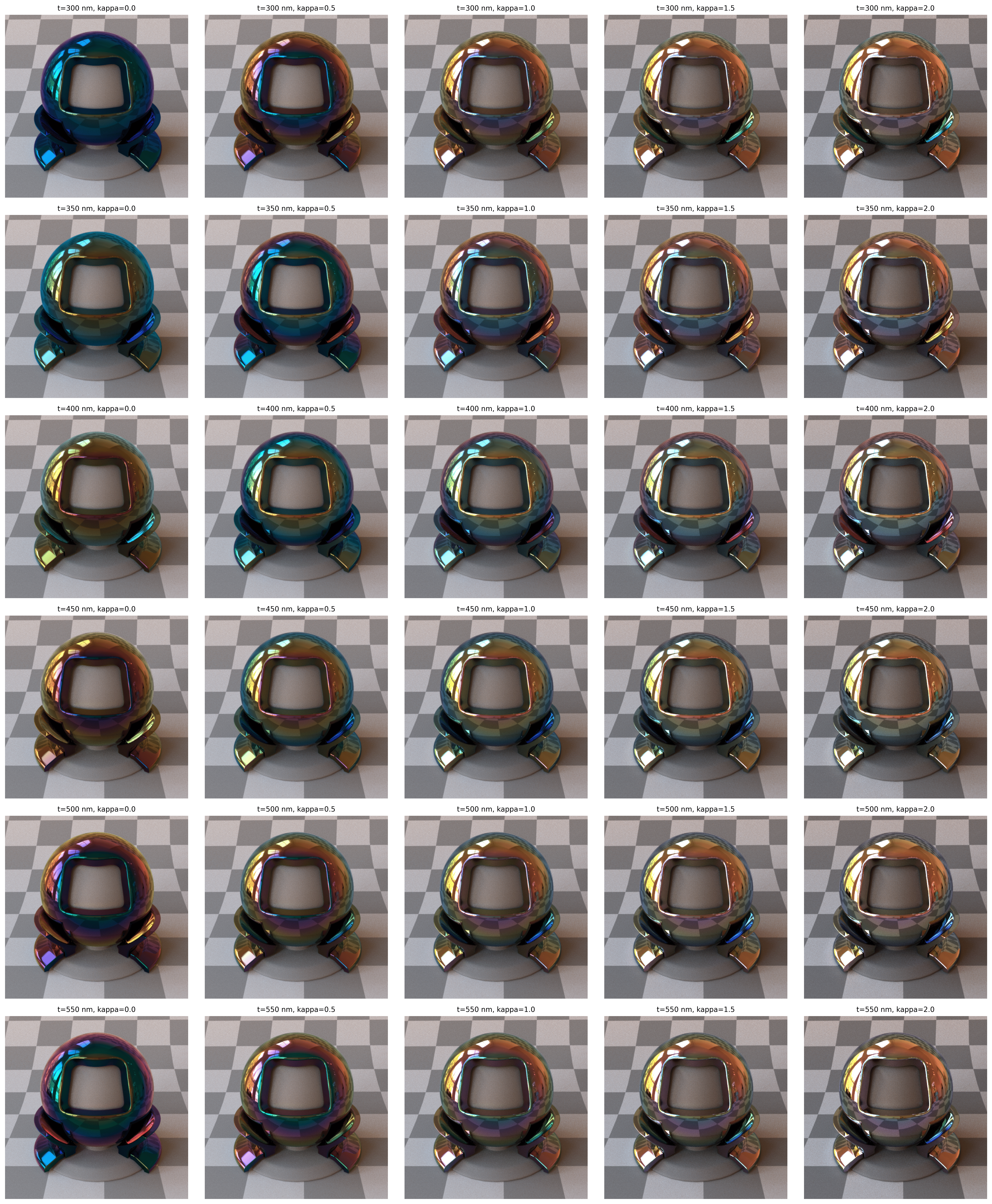
Parameter sweeps (film \(η=1.33\)):
Conclusion
Belcour’s thin-film BRDF slots neatly into a micro-facet framework once an analytical band integration is available. The Fourier-domain trick keeps evaluation fast enough for interactive tweaking, and the rendered steel convincingly reproduces real iridescent hues.
Future work: importance-sample the interference term for fewer Monte-Carlo samples, and extend to spatially varying film thickness maps captured from real objects.